Ac Battery Wiring Diagram : Installation Diagrams Consumption Measurement Sonnen Support Australia / It shows the way the electrical wires are interconnected and can also show where fixtures and components.
Ac Battery Wiring Diagram : Installation Diagrams Consumption Measurement Sonnen Support Australia / It shows the way the electrical wires are interconnected and can also show where fixtures and components.. Use the diagram as you follow the steps below. The premiere of the japanese car acura tl took place in 1995, when honda introduced the world a new luxury car in the already famous acura series. Simple car battery charger and indicator circuit diagram oct 13, 2015car battery charger circuit working principle: You will notice on these diagrams that the coming. Battery wiring to the sp pro is common, regardless of the application.
Here we have taken a 24v/230v inverter for converting 24v dc to 230v ac as our electrical equipment can run only in ac supply. Make terminal and circuit breaker connections. Rv solar controller wiring to a 12volt battery rv solar. Electrical wiring diagrams are composed of two things: This diagram shows a simple parallel circuit to increase current or power.
Generator Settings On The Sunny Island For Off Grid Systems Sunny Sma Corporate Blog from www.sma-sunny.com Help running a second battery and power ac wire diagram for 2008 fleetwood discovery. How to read ac or air conditioner condenser unit wiring diagram / schematic. This is a simple car battery charger with indication. F53 wiring diagram battery data schematic diagram. Read or download battery capacitor wiring diagram for free wiring diagram at mediagrame.museogilardi.it. A wiring diagram is a straightforward visual representation in the physical connections and physical layout of an electrical system or circuit. The premiere of the japanese car acura tl took place in 1995, when honda introduced the world a new luxury car in the already famous acura series. Always install fuse protection on any positive wiring connected to batteries.
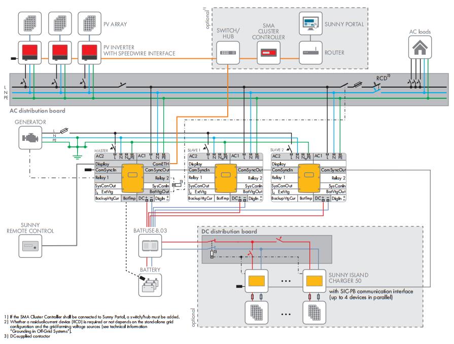
Black = phase or line, white = neutral and green/yellow = earth conductor.
Safe handling of lithium batteries guide 3.1 schematic diagram of solution. Do not work on any part of an ac installation unless you have the required expertise yourself. You will notice on these diagrams that the coming. Always install fuse protection on any positive wiring connected to batteries. It shows the way the electrical wires are interconnected and can also show where fixtures and components. You can download all the image about home and design for free. This helps even out the charging / discharging. What voltage do home outlets use? Copper is used for creating electrical dual battery capacitor wiring diagram s as a consequence of its properties which make it a great metal for this function. 24v to 220v 1000w dc ac sine wave inverter for photovoltaic solar system. Benefits of a microcare inverter. 2007 jeep grand cherokee wiring diagram. Battery charger and alternator issues and battery.
The below schematic diagram shows the main battery isolator, battery sense isolator and included temperature. Find instructions, manuals and troubleshooting help. Power & control wiring trending. Watch jeff's video on battery wiring below Cables are either connected to the opposite.
Mtd Fuses Diagram Wiring Diagram 131 Quit from i.pinimg.com Then they connect as many groups in series as needed. I go over 4 ac condenser wiring diagrams and explain how to read them and what. The complete circuit diagram for the proposed 500 watt inverter with battery charger can be seen below: Failure to do so or to follow any of the instructions or warnings in this document can result in electrical 3. Do not work on any part of an ac installation unless you have the required expertise yourself. Wiring diagram a wiring diagram shows, as closely as possible, the actual location of all black wires are conventionally used in power circuits and red wire in control circuits for ac magnetic wiring diagram. The same concept has been already elaborately discussed in one basically, the inverter uses the same transformer for charging the battery and for converting the battery power to 220 v ac output. These are our most commonly requested wiring diagrams, suitable for typical customer needs.
Icons that stand for the elements in the circuit, and also lines that represent the connections in between them.
Safe handling of lithium batteries guide 3.1 schematic diagram of solution. Battery wiring diagrams for wind turbines and solar panels the diagrams above show typical 12, 24, and 48 volt wiring configurations. Battery wiring to the sp pro is common, regardless of the application. Make terminal and circuit breaker connections. Simple car battery charger and indicator circuit diagram oct 13, 2015car battery charger circuit working principle: Wiring diagram 0 1 2 3 main switch uadr wiring diagram ac. Power & control wiring trending. If bbox in if bbox in left hand end of frame ab:2 b ab:0 b xc315:3. Black = phase or line, white = neutral and green/yellow = earth conductor. This post is called battery wiring diagram. When do i select solar control mode. Assume that we are using 12 volt batteries. 12v to 24v dc converter power supply circuit diagram.
Razor launch electric scooter parts. Make terminal and circuit breaker connections. 12v to 24v dc converter power supply circuit diagram. Icons that stand for the elements in the circuit, and also lines that represent the connections in between them. Wiring diagram 0 1 2 3 main switch uadr wiring diagram ac.
Bms1215s2 12v Setup Wiring Diagrams Redarc Electronics from www.redarc.com.au Battery charger and alternator issues and battery. The following diagram shows ac wiring only and indicates the generator connection and feed into the switchboard. Read or download battery capacitor wiring diagram for free wiring diagram at mediagrame.museogilardi.it. The power of all 3 batteries add to give us the effect of a battery 3 times as powerful but. What voltage do home outlets use? Let's say you have 4 cells in. The following battery wiring diagrams are. Electrical wiring diagrams are composed of two things:
Failure to do so or to follow any of the instructions or warnings in this document can result in electrical 3.
Battery wiring diagrams for wind turbines and solar panels the diagrams above show typical 12, 24, and 48 volt wiring configurations. The same concept has been already elaborately discussed in one basically, the inverter uses the same transformer for charging the battery and for converting the battery power to 220 v ac output. A wiring diagram is a simple visual representation of the physical connections and physical layout of an electrical system or circuit. When do i select solar control mode. What voltage do home outlets use? Assume that we are using 12 volt batteries. 2007 jeep grand cherokee wiring diagram. 12v fan on 230v circuit. Batteries can deliver extremely high current. Copper is used for creating electrical dual battery capacitor wiring diagram s as a consequence of its properties which make it a great metal for this function. You will notice on these diagrams that the coming. Then they connect as many groups in series as needed. Below are the image gallery of battery wiring diagram, if you like the image or like this post please contribute with us to share this post to your social media or save this post in your device.


0 Komentar